Omega Load Cell Wiring Diagram

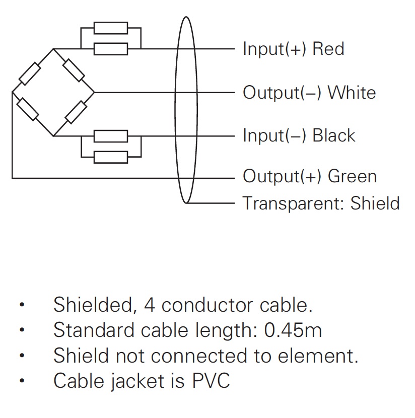
How To Wire A Load Cell Or A Bridge Sensor

Pin On Knowledge Base
Omega Engineering Data Acquisition Faq
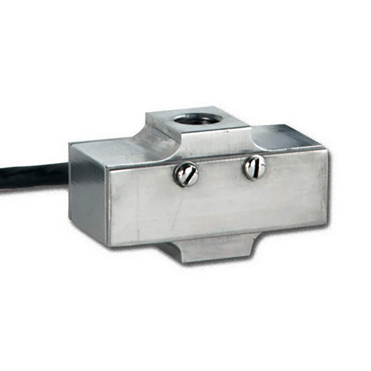
High Accuracy Stainless Steel S Beam Load Cells Omega

Rv Power Upgrade Live Breathe Move Beautiful Wiring Diagram For Solar Power System Electrical Wiring Diagram Rv Solar Rv Solar Panels

Pin On Plc

Keep in mind that if more than one laod sensor is connected to the same power supply you only need to connect the ground screw to only one ground otherwise a ground loop may be created causing additional noise.
Omega load cell wiring diagram.

How To Use Mq2 Gas Sensor Arduino Tutorial Arduino Arduino Projects Sensor
Load Cells
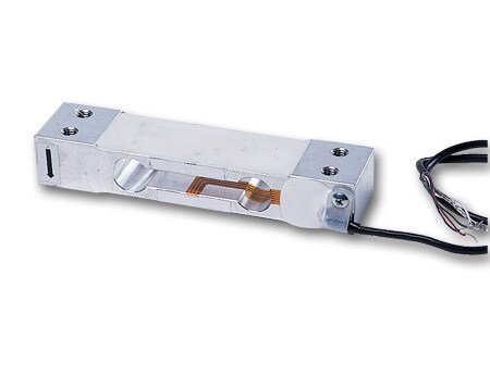
Beam Load Cell Discontinued See New Lc60 Omega Engineering

Arduino Lesson 11 Lcd Displays Part 1 Arduino Arduino Parts Arduino Projects

How To Wire Omega S Platinum Meter To An S Type Load Cell Youtube

Load Cell Wiring And Testing With Display Controller Youtube
Diy Cell Phone Detector Cell Phone Signal Electronic Circuit Projects Detector

Pin On Scheuberger

Enhanced Oil Recovery Market By Technologies Application Forecast 2025 Enhanced Oil Recovery Oils Marketing

Nokia 5110 Graphics Tutorial Arduino Projects Diy Arduino Projects Arduino

Arduino Security And Alarm System Project Goruntuler Ile Arduino Projeleri Arduino

Richard Nakka S Experimental Rocketry Site
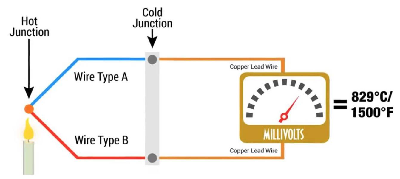
How Do Thermocouples Work Working Principles Of Thermocouples
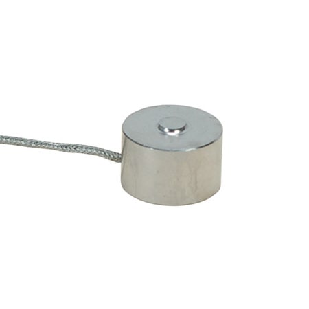
Subminiature Button Compression Load Cell Omega Engineering

What Is A Sensor Different Types Of Sensors With Applications Electronics Mini Projects Sensor Sensors Technology
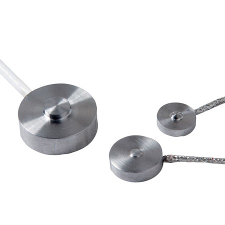
0 75 Diameter Miniature Button Compression Load Cell
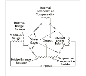
What Is A Wheatstone Bridge And Other Strain Gauges Circuits
Https Encrypted Tbn0 Gstatic Com Images Q Tbn 3aand9gcsa9pxp6wa4p58pkyvffyt Dpi7qyz2mo62ljux47guaaxpxd41 Usqp Cau
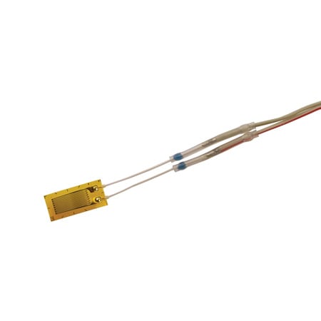
Pre Wired Strain Gauges For Easy Installation Omega

Faq How To Wire A Pressure Transducer 2 Wire 3 Wire Youtube

How To Test A Load Cell For Basic Functionality Engineering Tips Youtube

Pin On 1999 Chevy Tahoe Ls Snow Build

What Is A Load Cell And How Does It Work Explained Youtube
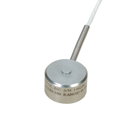
High Accuracy Miniature Button Compression Load Cell
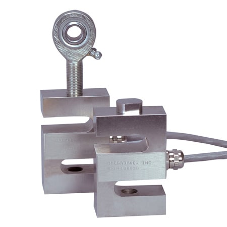
Stainless Steel S Beam Load Cells Omega Engineering
Miniature Low Profile Tension Compression Load Cells

Nd 3719 Strain Gauge Free Diagram
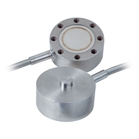
2 Diameter Miniature Button Compression Load Cell Omega
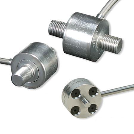
1 To 1 38 Diameter Threaded Miniature Inline Load Cells
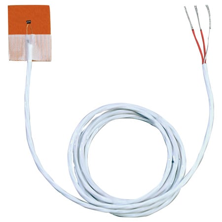
Self Adhesive Polyimide Fast Response Rtd Surface Sensors
Https Assets Omega Com Manuals M5692 Pdf

Diagram Wiring Diagram Hampton Breeze Full Version Hd Quality Hampton Breeze Kinesinschematic4198 Beautywell It
6qd5ohvxfpbum
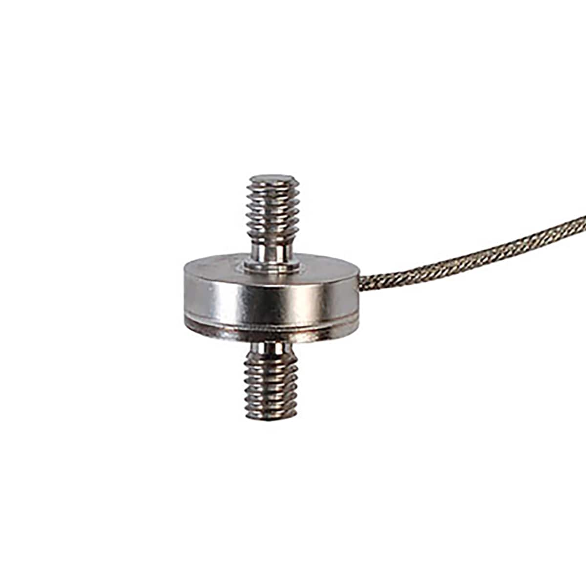
0 75 Diameter Threaded Miniature Inline Load Cells Omega
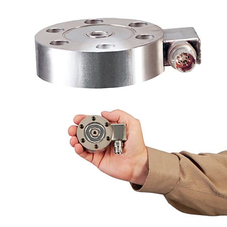
Ultra Low Profile Tension And Compression Load Cells

Lc712 50k Omega Load Cell Tension Links Lc712 Series
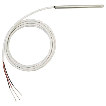
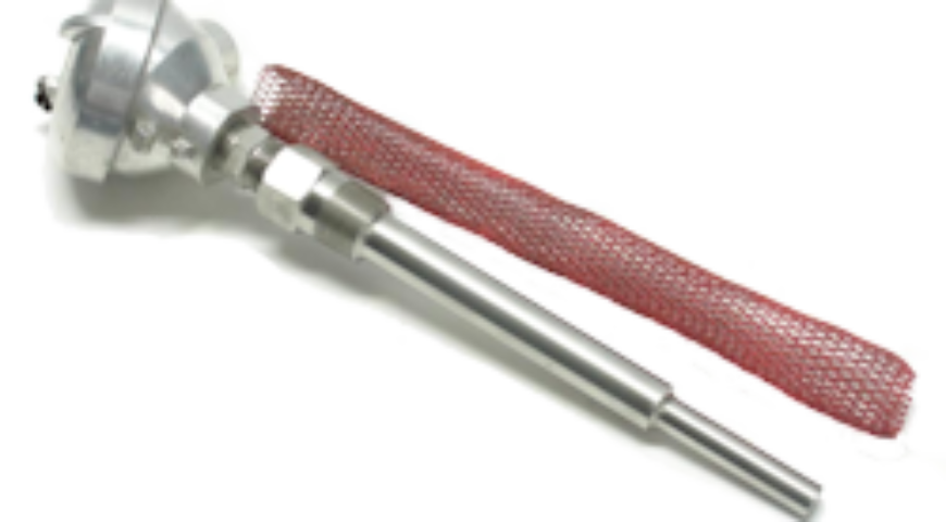
Pr 20 Series Short Rtd Probe Omega Engineering

A Piece Of Wire Of Resistance R Is Cut Into Five Equal Parts These Parts Are Then Connected I Youtube

How To Check The Load Cell With A Multimeter
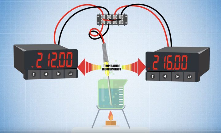
How Do You Split A Thermocouple Signal

3107 0 Tpk 01 Bead Probe K Type Thermocouple 50 C To 200 C This K Type Thermocouple Measures Temperatures From 50 C To 200 C And Connects To A Phidgets T
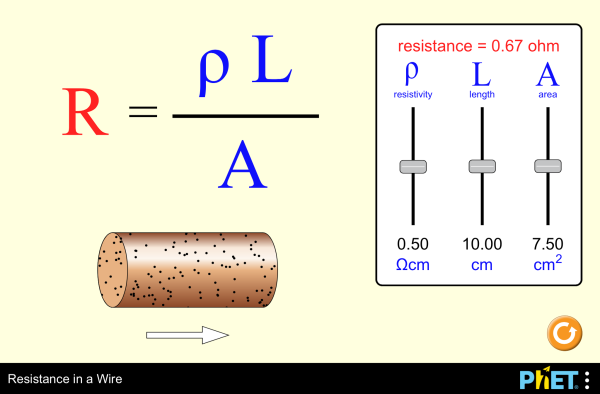
Resistance And Resistivity Physics
Https Encrypted Tbn0 Gstatic Com Images Q Tbn 3aand9gcsfl5 9rcauzwriqyqjqmmp685kvddvn3yf2sj1jav8yzbjj1bi Usqp Cau
Source : pinterest.com
